HYTBBW column-mounted high-voltage reactive power compensation device


product description
HYTBBW series high-voltage line reactive power compensation intelligent device is mainly suitable for 10kV (or 6kV) distribution lines and user terminals, and can be installed on overhead line poles with a maximum working voltage of 12kV. It is used to improve power factor, reduce line loss, save electric energy and improve voltage quality. Realize the automatic compensation of reactive power, so that the power quality and compensation quantity can reach the best value. It can also be used for reactive power compensation of 10kV (or 6kV) bus bars in miniaturized terminal substations.
The device is equipped with a special vacuum switch for capacitors and a microcomputer intelligent controller, and automatically switches the capacitor bank according to the reactive power demand and power factor of the line. Realize the automatic compensation of reactive power, make the power quality and compensation capacity reach the best value; and have automatic protection measures to ensure the safe operation of switches and capacitors. The device has the advantages of high degree of automation, good breaking reliability, no need for debugging, convenient installation, and obvious effect of energy saving and loss reduction. It is an ideal product for automatic switching of reactive power compensation capacitor banks in high-voltage lines. It can meet the intelligent requirements of the power system.
product model
Model Description

Technical Parameters
Structure and working principle
Device structure
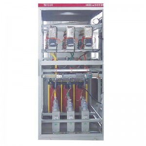
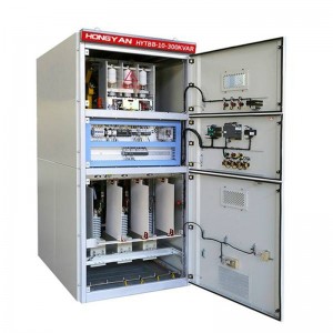
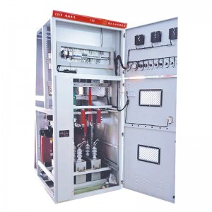
The device is composed of a high-voltage capacitor switching device, a microcomputer automatic control box, an outdoor open-type current sensor, a drop-out fuse, and a zinc oxide arrester.
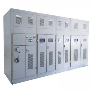
The high-voltage capacitor switching device adopts an integrated box structure, that is, all-film high-voltage shunt capacitors, capacitor dedicated (vacuum) switching switches, power supply voltage transformers, capacitor protection current transformers (non-power supply side sampling current transformers) and other components Assembled in a box, easy to install on site. The switching device and the microcomputer automatic control box are connected by aviation cables to ensure a sufficient safety distance. When the main equipment is not powered off, it can be operated on the controller, providing safe and convenient operation.
Working principle of the device
Close the drop-out fuse, connect the high-voltage power supply of the device, connect the secondary circuit AC220V power supply, and the high-voltage capacitor automatic controller (hereinafter referred to as the automatic controller) starts to work. When the line voltage, or power factor, or running time, or no When the power is within the preset switching range, the automatic controller connects the closing circuit of the special switching switch for capacitors, and the special switching switch for capacitors pulls in to put the capacitor bank into line operation. When the line voltage, or power factor, or running time, or reactive power is within the cut-off range, the automatic controller connects the tripping circuit, and the dedicated switching switch for capacitors trips to stop the capacitor bank from running. Thus realizing the automatic switching of the capacitor. To achieve the purpose of improving power factor, reducing line loss, saving electric energy and improving voltage quality.
Control mode and protection function
Control mode: manual and automatic
Manual operation: Manually operate the button on the control box on site to activate the vacuum contactor, and operate the drop-out fuse with an insulating rod.
Automatic operation: through the preset value of the device’s own intelligent reactive power controller, the capacitor is automatically switched according to the selected parameters. (Short-range and remote control functions can also be provided according to user requirements)
Control method: With intelligent logic control function, it must have automatic control methods such as voltage control, time control, voltage time control, power factor control, and voltage reactive power control.
Voltage control mode: track the fluctuation of voltage, set the voltage switching threshold and switch capacitors.
Time control method: several time periods can be set every day, and the switching time period can be set for control.
Voltage time control mode: Two time periods can be set every day, and the time period is controlled according to the voltage control mode.
Power factor control mode: use the controller to automatically calculate the grid status after switching, and control the capacitor bank switching according to the power factor control mode.
Voltage and reactive power control method: control according to the voltage and reactive power nine-zone diagram.
Protective function
The controller is equipped with short circuit protection, overvoltage protection, voltage loss protection, overcurrent protection, phase loss protection, switching delay protection (10 minutes protection, to prevent capacitors from being charged), anti-oscillation switching protection, and daily switching times Protection functions such as limit protection.
Data logging function
In addition to basic control functions, the controller must also have distribution network operation data and other data records.
Recording function:
Line real-time voltage, current, power factor, active power, reactive power, total harmonic distortion and other parameters query;
Real-time data statistical storage on the hour every day: including voltage, current, power factor, active power, reactive power, total harmonic distortion rate and other parameters
Daily line extreme data statistical storage: including voltage, current, active power, reactive power, power factor, maximum value, minimum value and occurrence time of total harmonic distortion rate.
Every day capacitor bank action statistics storage; including action times, action objects, action properties (protection action, automatic switching), action voltage, current, power factor, active power, active power and other parameters. The input and removal of the capacitor bank are each counted as one action.
The above historical data shall be fully stored for no less than 90 days.
Other parameters
Conditions of Use
●Natural environmental conditions
●Installation location: outdoor
●Altitude: <2000m<>
●Ambient temperature: -35°C~+45°C (-40°C storage and transportation allowed)
●Relative humidity: the daily average is not more than 95%, the monthly average is not more than 90% (at 25 ℃)
●Maximum wind speed: 35m/s
Pollution level: The specific creepage distance of each external insulation of III (IV) devices is not less than 3.2cm/kV
●Earthquake intensity: Intensity 8, ground horizontal acceleration 0.25q, vertical acceleration 0.3q
system condition
●Rated voltage: 10kV (6kV)
●Rated frequency: 50Hz
●Grounding method: neutral point is not grounded