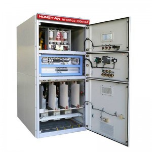
HYTBB series medium and high voltage reactive power compensation device-cabinet type


product description
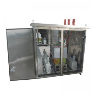
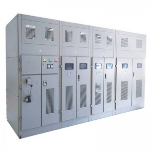
This device adopts a fully enclosed cabinet with high protection level. Each set of closed cabinets has live and current display components, which can be installed independently or combined with KYN28/KYN61 switch cabinets.
This device is a fixed compensation method, and manual and automatic group switching can also be used according to user requirements.
product model
Working method and characteristics
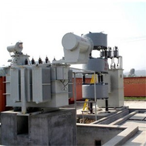
1. The devices mainly include high-voltage shunt capacitor bank, series reactor, capacitor switching switch vacuum contactor (vacuum switch), current transformer, zinc oxide arrester, reactive power automatic compensation controller, special microcomputer protection unit for capacitors, digital voltage Ammeter, temperature control fan device, electromagnetic lock sensor insulator, cabinet accessories, etc.
2. The device adopts advanced digital (or automatic power factor according to reactive power demand) grouping method, and binary codes capacitors with different capacities. Through automatic optimization combination, it can be realized with the least number of capacitor groups and the least high-voltage vacuum switches. The most series of capacity adjustment will not cause a substantial increase in cost, and has a good performance-price ratio. It can also be configured according to the user’s requirements, switching step by step.
3. The spray-by-type fuse is connected in series with the capacitor. When a part of the capacitor (50%~70%) in series breaks down, the fuse will act, and the faulty capacitor will be removed from the capacitor bank quickly, effectively preventing the fault from expanding (200kvar The above adopts the internal fuse protection method).
4. The discharge coil is connected in parallel to the capacitor circuit. When the capacitor bank is out of operation from the power supply, the residual voltage on the capacitor can drop from the peak value of the rated voltage to below 50v within five seconds.
5. The series reactor is connected in series in the capacitor circuit to limit the high-order harmonics in the switching capacitor bank and reduce the closing inrush current. The reactance rate of the series reactor is only 0.1~1% for limiting the inrush current, and for limiting the five times For the above harmonics, select 4.5%~6%, and for suppressing harmonics above the third, select 12%~13%.
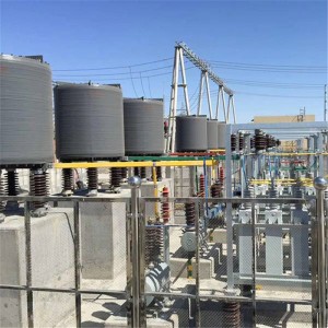
6. Reasonable structural design, good thermal and dynamic stability. The cabinet-type charged display device is mainly used to display the charged state of the device, and has a program lock, an observation window, and a forced locking function; the outdoor device has a fence, and the cabinet door adopts bolts Closed by rotation, it is more safe and reliable to ensure the safety of operation and maintenance personnel. The observation window of the cabinet door adopts mesh CNC punching and double-layer explosion-proof glass. The design concept is all-round and reliable. The top of the cabinet is equipped with a geographical pressure relief cover to prevent short circuit in the cabinet. The instantaneous pressure cannot be released, and the safety of operation and the appearance of the equipment have reached the international technical level.
7. The external dimensions, colors and wiring methods of the device can be designed according to user requirements
8. The high-voltage reactive power compensation controller is used to automatically control the switching of capacitors, with a high degree of automation and complete functions of measurement, display, control, and communication. It can switch capacitor banks according to reactive power and automatically compensate for reactive power of loads without manual intervention. , The power factor is above 0.95, it will exit automatically in case of external failure or power failure, and it will automatically resume operation after power transmission.
9. A microcomputer protection unit is used to protect the device, which has the functions of two-phase current differential protection and open triangle protection. When each group of capacitors fails, the microcomputer protection unit cuts off and blocks the group of capacitors, and other capacitor groups operate normally.
10. The device is allowed to operate for a long time at power frequency 1.1 times the rated voltage
11. The device is allowed to operate continuously under steady-state overcurrent whose effective value is 1.3 times the rated current due to overvoltage and high-order harmonics.
Technical Parameters
Features
●Using high-quality three-phase power capacitors, low operating temperature rise, high discharge initial voltage, good sealing and high reliability;
The capacitor has a built-in discharge element, and after the compensation device is disconnected from the grid, the residual voltage can be reduced below 50V within 3 minutes;
●Improve the power factor of electrical equipment, which can be increased to more than 0.95, and the current can be reduced by 10~20%;
●Improve equipment operation efficiency and reduce line reactive power loss;
●Improve the quality of power supply, increase the output of electrical equipment, increase the load rate of transformers and the efficiency of electrical equipment; increase power supply capacity;
●It is equipped with a high-voltage live display, electromagnetic lock, observation window, and has the function of forced locking.
●Reasonable structural design, easy to use, and synchronous switching with the motor.
Technical Parameters
●Rated voltage: 10 (6) 35kV
●Rated frequency: 50Hz
●Rated capacity: 50~20000kvar
●Neutral point connection mode: non-effective grounding or neutral point insulation.
Other parameters
Conditions of Use
●Installation location: indoor/outdoor
●Ambient temperature: -40°C~+45°C
●Relative humidity: ≤90% (25°C)
●Altitude: ≤4500 meters
●The installation site should be free from severe mechanical vibration, harmful gas and steam, conductive or explosive dust.