HYTSF series low voltage dynamic filter compensation device


product description
The company applies advanced power electronic technology and intelligent control technology, and adopts effective technical means such as science and economy, which not only solves the switching problem of shunt capacitor compensation under harmonic conditions, but also suppresses the problem according to the actual situation and requirements of users. Or control harmonics, clean power supply network and improve power factor. Therefore, this product is a new product with high technological content, advanced technology and reliable technology in the field of low-voltage harmonic control.
working principle
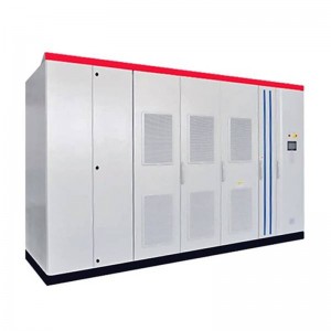
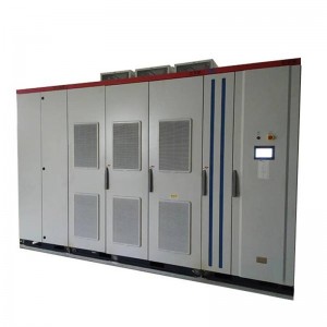
The important components of TSF low-voltage dynamic filter and compensation device are: monitoring unit, switch module, filter capacitor, filter reactor, circuit breaker, control system and protection system, cabinet, etc.
The capacitance of the capacitor in the TSF low-voltage dynamic filter and compensation device is determined according to the reactive power required to be compensated by the system at the fundamental frequency; while the selection basis for the inductance value in the LC circuit is: Produce series resonance with the capacitor, so that the device forms a very low impedance (close to zero) at the sub-harmonic frequency, allowing most of the harmonic current to flow into the device instead of the power supply system, improving the harmonics of the power supply system Wave voltage distortion rate, and at the same time, a shunt capacitor is installed in the complete device for fast dynamic reactive power compensation, which can meet the needs of fast changing loads.
The TSF passive filter compensation device adopts single-tuned LC passive filter compensation technology, and is designed according to the user’s site harmonic conditions. The harmonics filtered out by a typical filter compensation device are generally divided into: 3rd (150Hz), 5th (250Hz), 7th (350Hz), 11th (550Hz), 13th (650Hz) and so on.
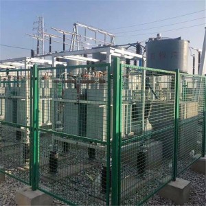
The TSF low-voltage dynamic filter and compensation device is connected in parallel with the load.
product model
Product application field
Electric arc furnace (arc cut-off and open circuit phenomenon will occur during the melting period, resulting in unbalanced current of each phase, voltage flicker, low power factor, and 2~7 high-order harmonics, which seriously affect the power quality of the power grid);
Traction substations powered by electric locomotives (for 6-pulse or 12-pulse rectifiers, generating 5th, 7th, and 1113th high-order harmonics, and changing loads can cause impacts on the power grid at any time);
●Large hoists in ports and coal mines (strong impact loads, fast load changes, and large changes, the current is instantly added to full load during hoisting, and the rest of the time is almost no-load. And the rectifier that supplies power to it is a typical harmonic source. impact on the power grid);
●Electrolyzer (powered by a rectifier transformer, the working current is very large, the rectifier will generate 5th, 7th, 11th, 13th high-order harmonics, which will affect the power quality);
●Wind and photovoltaic power generation (photovoltaic and wind power storage inverter and cluster grid-connected power supply, need to stabilize voltage, filter harmonics, compensation functions, etc.);
●Metallurgical industry/AC and DC rolling mills (rolling mills driven by AC speed-adjustable motors or DC motors can cause grid voltage fluctuations, and because of the presence of rectifiers, they also generate 5, 7, 11, 13, 23, and 25th higher harmonics , affecting power quality);
●Automotive production line (transmission, electric welding, painting and other devices are generally powered by 6-pulse or 12-pulse rectification, which generates 5, 7, 11, 13, 23, 25 harmonics and causes grid voltage fluctuations);
Drilling and paralleling platforms (generally powered by 6-pulse rectifiers, the 5th, 7th, 11th, and 13th harmonics are more serious, which increases the current in the system, reduces work efficiency, and requires a large amount of generator input);
●High-frequency welding machine, electric (spot) welding machine, intermediate frequency furnace (a typical rectifier-inverter device, and high-order harmonics generated by impact loads, which seriously affect the power quality of the grid);
●Smart buildings, large shopping malls, office buildings (a large number of fluorescent lamps, projection lamps, computers, elevators and other electrical equipment can cause serious distortion of voltage waveforms and affect power quality);
●National defense, aerospace (high-quality power supply scheme for cluster sensitive loads);
●The SFC system of the gas turbine power station (a typical rectifier-inverter device, which generates high-order harmonics of 5, 7, 11, 13, 23, 25, etc., seriously affects the power quality of the grid.
Technical Parameters
Features
●Zero-current switching: Adopt high-power thyristor current zero-crossing switching technology to realize zero-current input and zero-current cut-off, no inrush current, no impact (vacuum AC contact is optional).
●Fast dynamic response: fast tracking system load reactive power changes, real-time dynamic response switching, system response time ≤ 20ms.
●Intelligent management: take the real-time reactive power of the load as the switching physical quantity, apply the instantaneous reactive power control theory, and complete data collection, calculation and control output within 10ms. Realize instantaneous switching control, power distribution parameters, power quality and other data, and can realize online monitoring and remote control, remote signaling, and remote adjustment.
●The device has multiple protection functions: over-voltage and under-voltage protection, power-off protection, short-circuit and over-current protection, temperature control protection, power-off protection, etc.
●Device display content: 11 electrical parameters such as voltage, current, reactive power, active power, power factor, etc.
●Single-tuning compensation circuit capacitor adopts anti-harmonic capacitor Y connection.
technical performance
●Rated voltage: 220V, 400V, 690V, 770V, 1140V
●Fundamental frequency: 50Hz, 60Hz.
●Dynamic response time: ≤20ms.
●Harmonic measurement range: 1~50 times
●Fundamental wave reactive power compensation: the power factor can reach above 0.92-0.95.
●The filtering effect meets the requirements of the national standard GB/T 14549-1993 “Power Quality Harmonics of Public Grid”.
●Filter harmonic order: 3rd, 5th, 7th, 11th, 13th, 17th, 19th, 23rd, 25th, etc.
●Voltage stability range: meet the requirements of the national standard GB 12326-199.
●Harmonic current absorption rate: 70% for dry 5th harmonic on average, 75% for dry 7th harmonic on average.
●Protection grade: IP2X
Other parameters
Environmental conditions
●The installation site is indoors, without severe vibration and impact.
●Ambient temperature range: -25°C~+45°C
●At 25℃, relative humidity: ≤95%
● Altitude: no more than 2000 meters.
●There is no explosive and flammable medium around, no gas enough to damage insulation and corrode metal, no conductive dust.
Technical Services
●On-site detection and analysis of customer harmonics and submit a test report.
●According to the customer’s on-site situation, propose a plan
●Determination of customer’s harmonic control plan and harmonic transformation.
●Reactive power testing, determination and modification of reactive power compensation scheme.
Dimensions
Technical Services
On-site detection and analysis of customer harmonics and a test report.
Propose a plan according to the customer’s on-site situation.
Determination of customer harmonic control plan and harmonic transformation.
Test of reactive power, determination and transformation of reactive power compensation scheme.
Parameters required for ordering
The capacity of the power supply transformer; the primary and secondary voltages: short-circuit voltage; the primary and secondary wiring methods, etc.
The power factor of the load; the nature of the load (frequency conversion, DC speed regulation, intermediate frequency furnace, rectification), the current harmonic situation, it is best to have harmonic test data.
Environmental conditions and degree of protection at the installation site.
The required power factor and harmonic distortion rate and other requirements.